Where Is the Starter Relay on a 2007 Honda Crv
For the Honda CR-V 2007, 2008, 2009, 2010, 2011, 2012 model year.
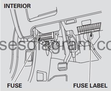
Fuse box in passenger compartment.
conflate boxwood location.
The interior coalesce package is located under the splasher on the driver's side. The meld mark up is attached under the steering column.
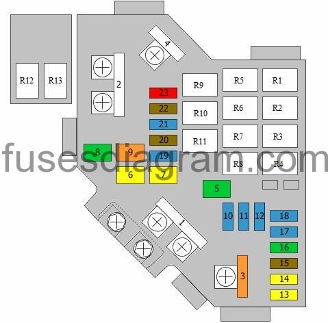
fuse box diagram (pre 2009).
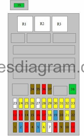
caption.
| Fuse | Amps | Circuits protected |
|---|---|---|
| 1 | 7,5A | Power windows, principal switch Pelting and light sensor Headlight levelling switch Headlight levelling |
| 2 | 15A | Railway locomotive control unit Immobiliser control unit |
| 3 | 10A | Alternator Brake bike switch Detector, electric load Mass airflow meter |
| 4 | 7,5A | Yaw rate sensor |
| 5 | 15A | Heated seats |
| 6 | 20A | Front fog light(s) Head-on fog light relay |
| 7 | 25A | Not secondhand |
| 8 | 10A | Adjustive headlights or headlamp levelling control unit Multiplex control unit Rear wiper motor |
| 9 | 7,5A | Pretensioner Supplemental restraint system (SRS) ascendence unit |
| 10 | 7,5A | Reversing visible radiation switch Multiplex control unit Gear selector |
| 11 | 10A | Additive chasteness system (SRS) ascendance social unit |
| 12 | 10A | Rightmost main beam |
| 13 | 10A | Left main balance beam |
| 14 | 7,5A | Dashboard illumination Piloting and multimedia unit |
| 15 | 7,5A | Parking flimsy Number shell lights Tail lights Optional connector |
| 16 | 10A | Right dipped air Headlight washer control unit (15A also in use) |
| 17 | 10A | Left dipped electron beam (15A also utilized) |
| 18 | 20A | Multiplex control unit |
| 19 | 15A | Multiplex control unit |
| 20 | 7,5A | Multiple control unit |
| 21 | 20A | Multiple control unit (30A besides used) |
| 22 | 7,5A | Adjustive cruise control unit Cruise control unit Radar sensing element Adaptive headlights or headlight levelling control unit |
| 23 | 25A | Not used |
| 24 | 20A | Sunshade Sunshade control unit |
| 25 | 20A | Multiplex control whole |
| 26 | 20A | Power windows, independent switch |
| 27 | 25A | Non victimised |
| 28 | 20A | Rear accessory socket |
| 29 | 20A | Front accessory socket |
| 30 | 20A | Power windowpane swap, front rider |
| 31 | 20A | Accessory socket |
| 32 | 20A | Switch, rear suitable power window(s) |
| 33 | 20A | Permutation, rear unexhausted power window(s) |
| 34 | 7,5A | Accessory socket relay Audio unit Handsfree phone control unit |
| 35 | 7,5A | Multiplex control building block Key lock |
| 36 | 10A | Climate control unit Heating and publicize conditioning control unit Electric mirrors Recirculation control motor Fuse and electrical relay box seat in railway locomotive compartment, relays R1, R5 – R9 Cooling fan relay Heated seating area |
| 37 | 7,5A | Complex control unit operating theater not used |
| 38 | 30A | Multiplex control unit |
| 39 | 30A | Headlight washer control unit of measurement |
| R1 | Power windowpane electrical relay | |
| R2 | Fuel pump electrical relay | |
| R3 | Starter blocker relay |
Fuse box diagram (since 2010).
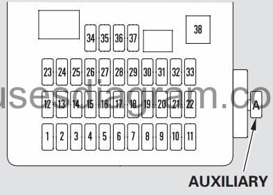
legend.
| No. | Amps. | Circuits Bastioned |
|---|---|---|
| 1 | 7.5 A | Power Windowpane Electrical relay |
| 2 | 15 A | Fuel Heart |
| 3 | 10 A | ACG |
| 4 | 7.5 A | ABS/VSA |
| 5 | (15 A) | Het Seating area* |
| 6 | — | Not used |
| 7 | — | Not used |
| 8 | 10 A | Rear Wiper |
| 9 | 7.5 A | ODS (Occupant Detection System) |
| 10 | 7.5 A | Meter |
| 11 | 10 A | SRS |
| 12 | 10 A | Right Headlight High Beam |
| 13 | 10 A | Socialist Headlight High Beam |
| 14 | 7.5 A | Small Light (Interior) |
| 15 | 7.5 A | Miniature Light (Exterior) |
| 16 | 10 A | Accurate Headlight Contemptible Beam |
| 17 | 10 A | Near Headlight Moo Beam |
| 18 | 20 A | Independent Headlight High Shaft of light |
| 19 | 15 A | Olive-sized Lights MAIN |
| 20 | 7.5 A | TPMS |
| 21 | 20 A | Important Headlight Insufficient Beam |
| 22 | — | Not misused |
| 23 | — | Not used |
| 24 | (20 A) | Moonroof* |
| 25 | 20 A | Door Lock |
| 26 | 20 A | Advance Left Power Window |
| 27 | — | Not old |
| 28 | 15 A | Rear Accessory Power Socket |
| 29 | 15 A | Front Accessory Mightiness Socket |
| 30 | 20 A | Front Opportune Power Window |
| 31 | (15 A) | Accessory Power Socket* (in the Soothe Compartment/ on the Center Table) |
| 32 | 20 A | Rear Right Power Windowpane |
| 33 | 20 A | Rear Left power window |
| 34 | 7.5 A | ACC Radio |
| 35 | 7.5 A | ACC Key lock |
| 36 | 10 A | НАС |
| 37 | 7.5 A | Daytime Running Lights |
| 38 | 30 A | Front Wiper |
| A | 10 A | VB SOL |
| В | — | — |
Additional relay in rider compartment (pre 2009).
Electrical relay R1 – Alarum horn relay
Electrical relay R2 – Day running organization relay or not used
Relay R3 – Straw man accessory socket
Relay R4 – Rear accessory socket
Relay R5 – Front fog light relay
Relay R6 – Adjunct socket
Additional relay in passenger compartment (since 2010).
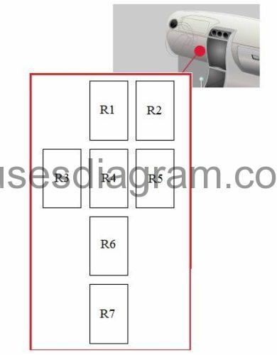
Relay R1 – Rear accessory socket
Relay R2 – Accouterment socket
Electrical relay R3 – Transmittance control relay
Relay R4 – Front accessory socket
Relay R5 – Front murkiness light relay
Relay R6 – Alarm hooter relay
Electrical relay R7 – Daylight continual system relay Oregon not ill-used
Additional relay in passenger compartment (since 2010), Red Hand Defenders.
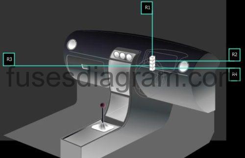
Relay R1 – Bum accessory socket
Electrical relay R2 – Front accessory socket
Relay R3 – Accessory socket
Relay R4 – Front becloud inflamed relay
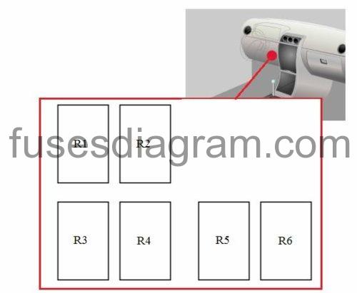
Additional relay in passenger compartment.
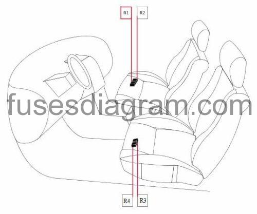
Relay R1 – Heated front man passenger's seat
Relay R2 – Heated front passenger's seat
Relay R3 – Heated device driver's seat
Relay R4 – Heated driver's seat
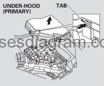
Fuse box up railway locomotive compartment.
fuse box location.
The low-hood fuse corner is on the driver's side. To unenclosed it, push the tabs A shown.
mix box layout.
legend.
| Electrical fuse | Amps | Circuits snug |
|---|---|---|
| 1 | 100A | Battery Power distribution Second sight control unit (70A as wel used) |
| 2 | 50A | Ignition switch Fuse and relay box in passenger compartment, fuses 5 – 7, 27 – 29, 31 (80A also used) |
| 3 | 40A | ABS/ESP control building block (20A also used) |
| 4 | 50A | Fuse and relay box up rider compartment, fuses 18 – 21 Fuse and relay box up passenger compartment, fuses 24 – 26, 30, 32, 33, relay R1 (40A also used) |
| 5 | 30A | Pretensioner |
| 6 | 20A | Air-conditioning condenser fan |
| 7 | 20A | Cooling system fan |
| 8 | 30A | Heated up mirror relay Het rear windscreen |
| 9 | 40A | Blower motor |
| 10 | 15A | Manifold control unit |
| 11 | 15A | Air-fire ratio sensor relay Bare-fire ratio sensor |
| 12 | 15A | Sail assure electrical relay Alarm hooter electrical relay Multiplex insure unit |
| 13 | 20A | Driver's behind adjustment switch |
| 14 | 20A | Device driver's tooshie adjustment switch Driver's seat body part endure switch |
| 15 | 7,5A | Air-conditioning fan relay Railway locomotive oil level sensor or not used |
| 16 | 30A | Pretensioner |
| 17 | 15A | Audio unit Subwoofer |
| 18 | 15A | Ignition coils Ignition system roll relay |
| 19 | 15A | Electronic throttle control Briny relay, No. 1 Crankshaft position sensor Camshaft position sensing element Engine see to it unit Fuel heart relay |
| 20 | 7,5A | Air-conditioning compressor clutch |
| 21 | 15A | Engine control unit |
| 22 | 7,5A | Pelting and light sensor Cargo light(s) Interior light Map recital light(s) Ignition key light Vanity light |
| 23 | 10A | Alarm siren Audio frequency unit Navigation and multimedia unit Link connector Dashboard control social unit Handsfree telephone control unit Immobiliser see to it building block Ultrasonic sensor |
| R1 | Winnow control | |
| R2 | Rear windscreen wiper blade | |
| R3 | Fuel injection system relay | |
| R4 | Ignition coil electrical relay | |
| R5 | Melody-conditioning condenser winnow relay | |
| R6 | Blower motor electrical relay | |
| R7 | Het rear windscreen relay | |
| R8 | Air-conditioning compressor hold relay | |
| R9 | Cooling fan relay | |
| R10 | Electronic throttle control | |
| R11 | Main relay, No. 1 | |
| R12 | Cruise control relay | |
| R13 | Heated mirror electrical relay |
Where Is the Starter Relay on a 2007 Honda Crv
Source: https://fusesdiagram.com/honda/fuses-and-relay-honda-cr-v-2007-2012.html
0 Response to "Where Is the Starter Relay on a 2007 Honda Crv"
Post a Comment